Problems,
Workarounds and
other stuff
Fixing the Regulator Misery -
German Approach
Those of you
daring to really fix up things with no compromise and wanting
to get rid of problems before they come up may also wander the
twisted path that I went down just recently.
Sitting in "The Lab" one morning at a very early hour and being quite
uninspired and bored I started digging in my boxes full of "unsorted
stuff". During that a bag fell into my hand containing no less than 4
of these switchmode voltage regulator modules for the bigger IBM
Netfinity machines (5600 or 6000R). They are designed for a single
+12VDC input and programmable between 1.3 - 3.5VDC output voltage @ up
to 16 Amps ... ready for the Pentium-III or Xeon.
Remembering the
problem I have with the overheating LT-1084CT 3.3V regulator on the
P-90 platform I thought it were a good idea to test out to substitute
the linear regulator with the SMVR and to "make it fit" in the 9595.
20 minutes later my 9595-B06 RAID-box ran with a P90 platform plus a
P-133 CPU (I had no faster spare at that point) and with the switchmode
regulator module from the Netfinity. The module gets merely hand-warm.
The bigger one of the two coils heats up a little - but that was it. No
comparison to the "space heater" LT-1084 with its flimsy heatsink.
+-----+  +---------.
|     |  |         .
| A  B|  |         . A = outer, lower row  -  B = inner, upper row
|     +--+         .
|                  .
| o  o  01         . N.C.                     N.C.
| o  o             . N.C.                     N.C.
| o  o             . N.C.                     N.C.
| #  #             . +12V input               +12V input
| #  o             . +12V input               Reserved
| o  o             . Ishare                   Output Enable
| #  o             . V-ID 0                   V-ID 1
| #  #             . V-ID 2                   V-ID 3
| o  o             . V-ID 4                   Power Good
| o  o             . V(out)                   GND
| o  o             . GND                      V(out)
| o  o             . V(out)                   GND
| o  o             . GND                      V(out)
| o  o             . V(out)                   GND
| o  o             . GND                      V(out)
| o  o             . V(out)                   GND
| o  o             . GND                      V(out)
| o  o             . V(out)                   GND
| o  o             . GND                      V(out)
| o  o  20         . V(out)                   GND
|                  .
|     +--+         .
|     |  |         .
|     |  |         .
+-----+  +---------.

           Voltage Regulator FRU 36L8906
           12V-only, step-down programmable
           Underside View

           (Pinout according to Intel Specs V8.1)
|
| Voltage Identification Code (partial) |
| VID4 |
VID3 |
VID2 |
VID1 |
VID0 |
V(out) |
|
| 1 |
1 |
1 |
1 |
1 |
Disabled |
| 1 |
1 |
1 |
1 |
0 |
2.1 |
| 1 |
1 |
1 |
0 |
1 |
2.2 |
| 1 |
1 |
1 |
0 |
0 |
2.3 |
| 1 |
1 |
0 |
1 |
1 |
2.4 |
| 1 |
1 |
0 |
1 |
0 |
2.5 |
| 1 |
1 |
0 |
0 |
1 |
2.6 |
| 1 |
1 |
0 |
0 |
0 |
2.7 |
| 1 |
0 |
1 |
1 |
1 |
2.8 |
| 1 |
0 |
1 |
1 |
0 |
2.9 |
| 1 |
0 |
1 |
0 |
1 |
3.0 |
| 1 |
0 |
1 |
0 |
0 |
3.1 |
| 1 |
0 |
0 |
1 |
1 |
3.2 |
| 1 |
0 |
0 |
1 |
0 |
3.3 |
| 1 |
0 |
0 |
0 |
1 |
3.4 |
| 1 |
0 |
0 |
0 |
0 |
3.5 |
"0" = tied to
GND, "1" = left open or tied to input voltage
|
As you can see on
the tables above: the pinout is pretty simple. The pins "#" in the
upper table are those which are of importance here. The lower table
shows the codings for the output voltage. The 3.3V setting is separated
from the rest of the table, which is only the half of it anyway. If
V(id)4 is tied to GND too the V(out) will be between 1.3V and 2.05VDC.
Since this is of no relevance for our purposes I gracefully left it
away.
Three Steps To Heaven
Step 1: Removing the LT-1084 and its heatsink
It is recommended
to operate carefully. Mindless ripping and careless acting with tools will
cause damage on the platform. Start with unsoldering the holder pin
for the heatsink first. It may need a bit more heat and a little
pulling force to come free. The heatsink fixing pin isn't electrically
connected to anything on the board - so it is not that
dramatically when the copper soldering pad / through-hole copper comes
off. Nontheless: try to avoid that.
Then unsolder the 3 terminals from the LT-1084. You might try
unsoldering all 3 at one time and pull out the chip by gently pulling
and wiggling it a bit sideways.
Then clear the area around the 3 solder holes and at least the middle
hole entirely from tin.
Check for left-over tin and potential short-circuits - and that was it
for this part.
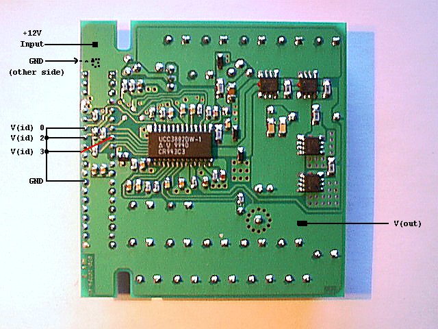
Step 2: preparing the Switchmode Voltage
Regulator
On my regulator the most of the upper copper surface is GND, the most
of the lower is either +12V input or V(out). I decided not to bother
with any sort of "plug" or whatever row of contacts. Just
straightforward solder the wires as tight and direct as possible. So I
scratched a 2 by 6 mm spot clear from paint on the GND plane and on the
+12V input plane and soldered two thick wires directly to the board.
The opposite end of these wires carry a standard DC plug to fit in the
9595 power supply. Later I used a male-female combo (as for these silly
processor fans) not to loose a DC plug on the power supply.
Some thin "patch wires" connect the pins V(id)0, V(id)2 and V(id3) with
the nearest GND pin. Pick any - there are many.
Bench-testing with a bare 95 power supply gives a straight 3.34VDC
output on the V(out) plane / pins. The voltage did not drop
significantly when being loaded with 6 Amps (a couple of parallel 25W
resistors / 4.7 Ohm).
Heat-emmission: almost none. The converter coil L2 gets a bit warm.
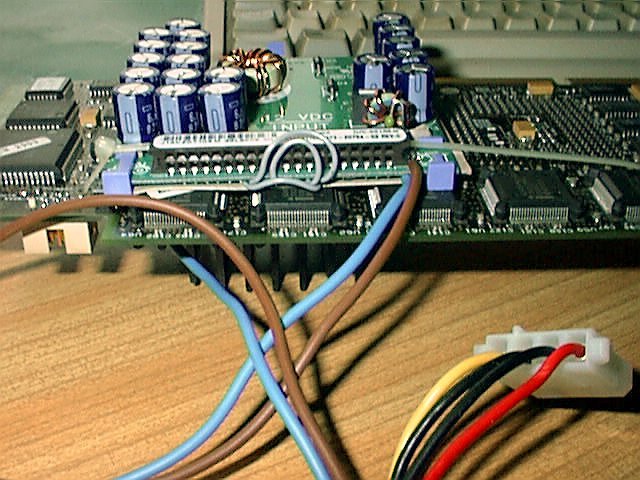
Step 3: Installing on the P90 Platform
Now: there are no
provisions for fixing the regulator elsewhere. The simpliest method was
just to strap it onto the upper side of the processor platform.
It is relatively flat, there is room (given you don't have a long MCA
board installed in the bottom-most slot #8) and the way down to the
power supply as well as to the solder pads of the removed LT-1084 is
pretty short.
The output voltage is fed with a short, thick piece of isolated silver
wire (dia. about 1mm) from the regulator down to the mid-pin of the
-removed- LT-chip. In addition I cut a piece of thin cardboard to act
as an insulator sheet between the regulator and the processorboard.
There are some larger holes in the P90 platform: one close to the
connector for the info-panel cable and one right from the 82497 cache
controller. You need two long and thin plastic cable straps ...
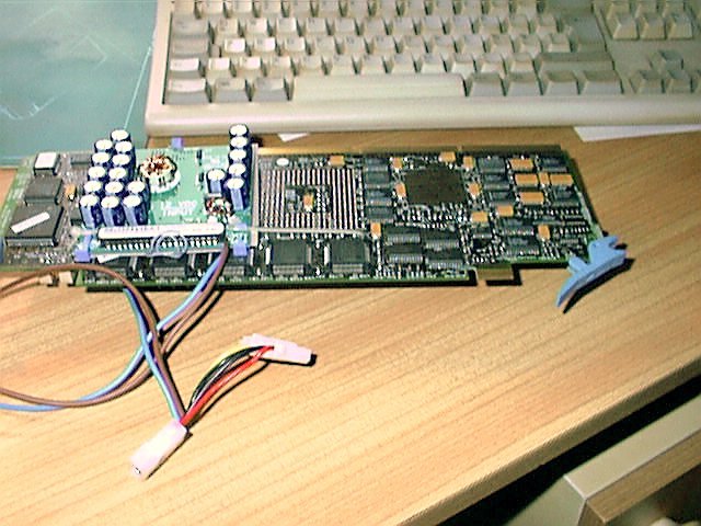
The result will probably look similar to that shown below:
Warning !
Watch Out !
Any mistake in the
combination of parts like e.g. using an 82496 +5V-only cache controller
instead of the 82497 or a falsely orientated / mis-aligned CPU will
cause massive damage !
The little LT-1084 regulator shuts down at latest 5 Amps .... but a
baby like that can pump up 16 Amps (or more !) into your circuit - fed
by a power supply that delivers 35 - 45 Amps at 12VDC. That will blow a
CPU out of the socket if it isn't in proper orientation. And will -
most likely - cause massive damage to the platform printboard itself.
Be Warned !
Back up
to the Top
|